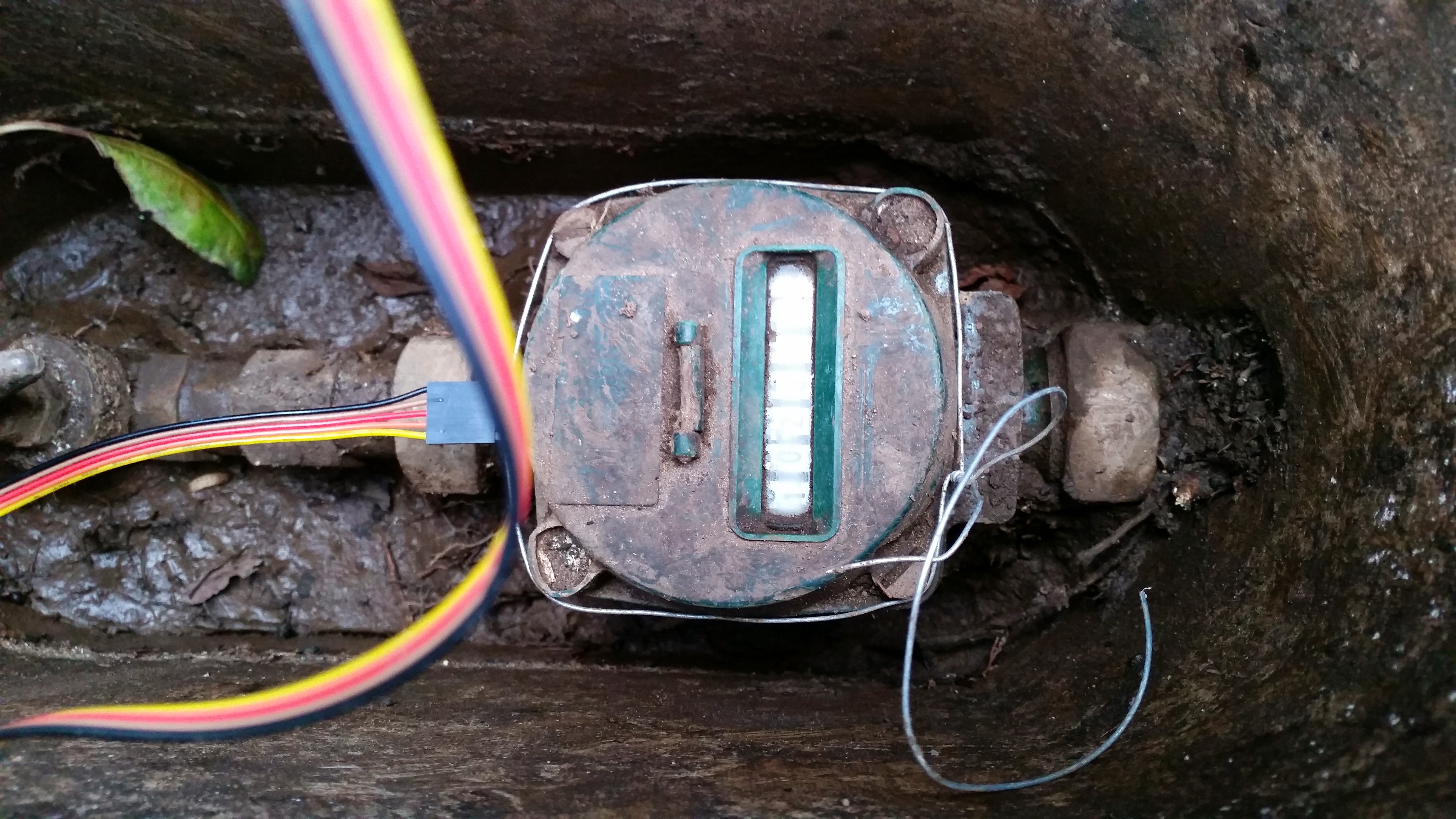
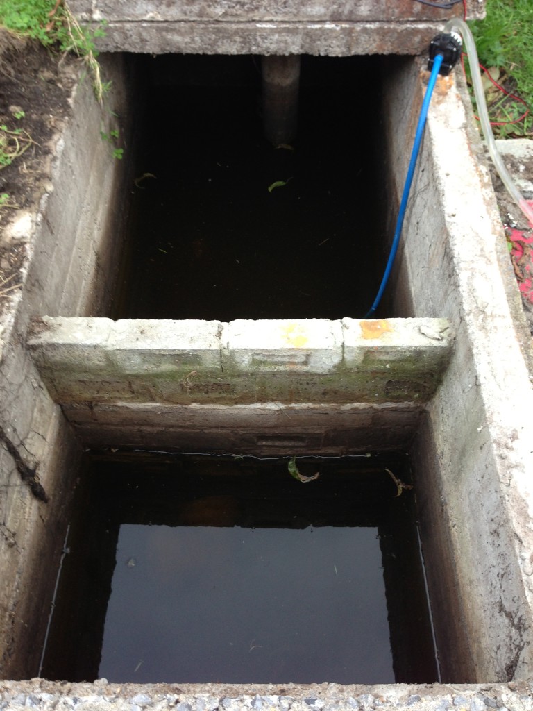
While I was away it seems I had some rain at home. Septic is half full again! Blast! Missed out on seeing how the water is getting in.
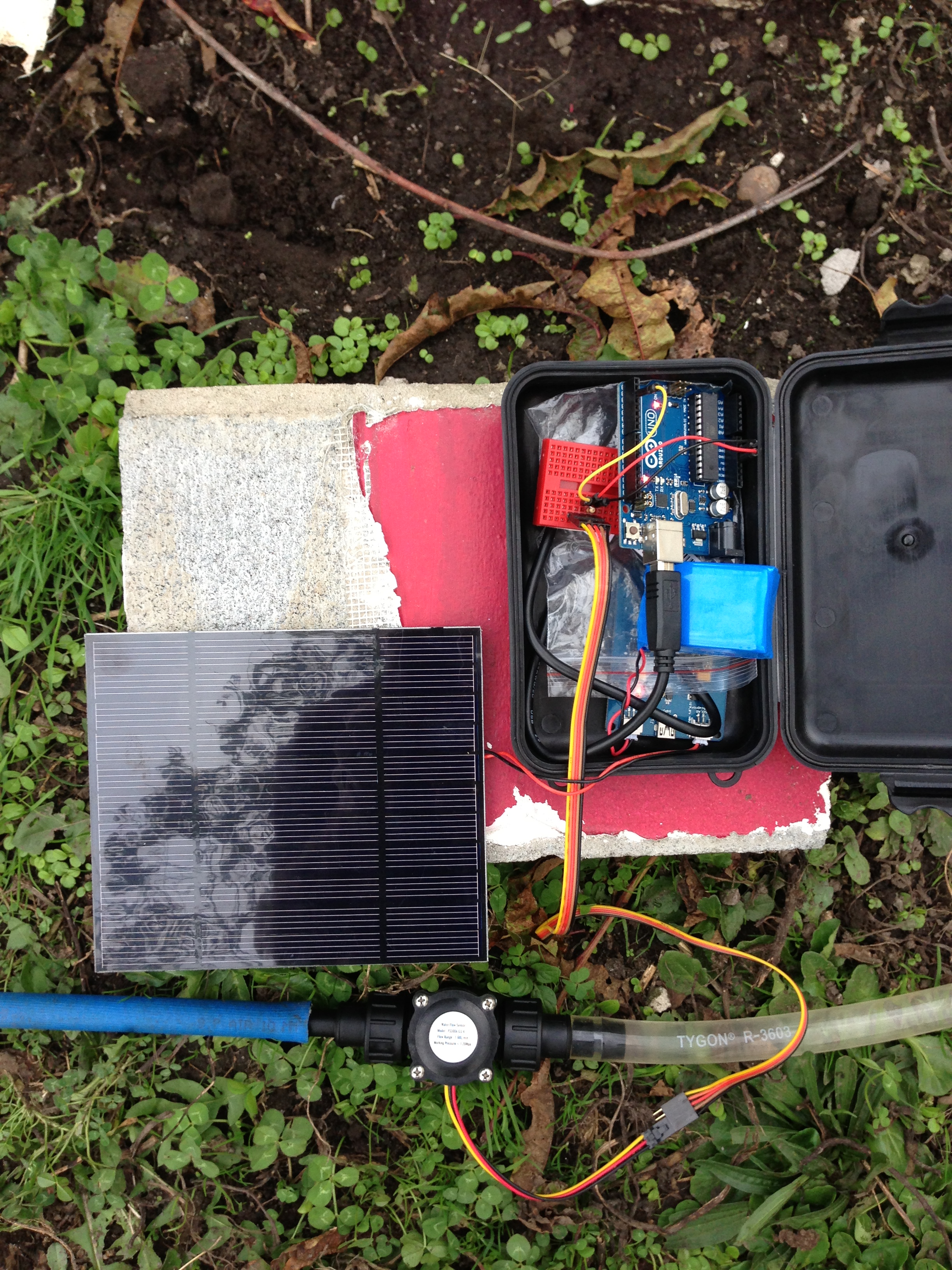
At least I have a good excuse to play with pumps again! This time to spice things up I thought I’d try and monitor how much water gets pumped out! Yeah! You can see in the above shot how small the pump is I’m using…. Does a good job lifting all that water so far. I slapped this beast together:
 Crammed in that little box we have a solar lithium battery charger hooked up to a 3.7V 3000mAh Li-ion batter and the biggest solar panel I have laying around….. I forget its watts but know it provides 3.6 on the voltage side of things. This in turn has an Arduino UNO plugged in. Portable powah! Wrangled off that we have a simple cheap water flow meter with a couple of standard poly pipe fittings to attach the hoses to. These can be had from any decent hardware store. It was looking like it may rain thus it all being crammed into the box. The plastic you can see in the box is a precaution to stop any of the circuitry shorting out across the 2 boards.
The pumps in the outlet line and the party is about to start! I had no problem getting the pump primed this time. I dicked around with it a whole lot the last time and got it down pat pretty well. Attach garden hose to output side of hose coming from the pump and push the water flow through backwards until all the air has blown out. Turn pump on and garden hose off and voila! Lots of flow!

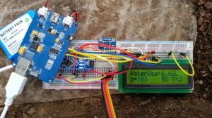
That pumped happily for a few hours no problems. Just on dark though it started to really rain so I packed the gear up just short of the tank being empty. No probs! I have stats to check off the Arduino! After unpacking it from the box carefully I realized a flaw in my plan….. How was I do get the data out of it? Ha! Foiled! Rebooting the Arduino would wipe said data. OK that’s great Ill just hook it up to USB and turn the serial port viewer on….NO! That auto causes the Arduino to reboot! Luckily the code I used verbatim from Adafruit had a 2×16 LCD hooked up to it that I decided not to bother with. Cool, cool. A bit more time and we were away…
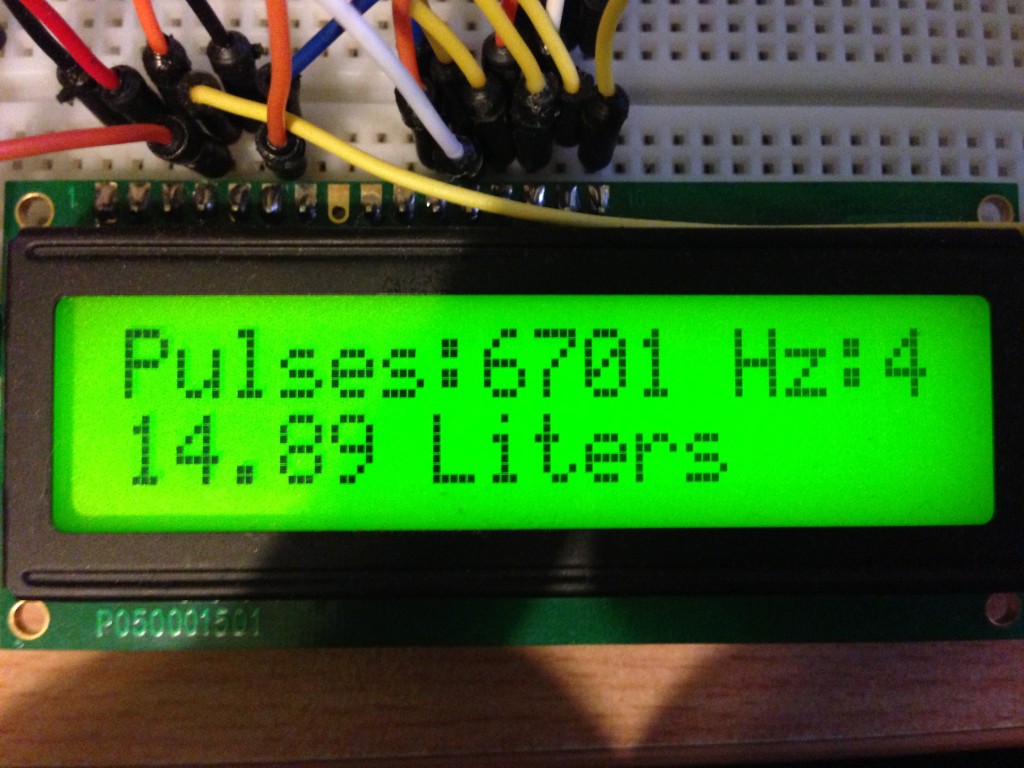
14.89 Litres?!?!?!?!! What is this black magic! Look at that water flowing in the pic up the page. That’s hundreds of litres over a few hours! Hundreds! I think what happened, and I’m sad to say it but I must of temporarily knocked the power from the little bread board or something. That or there wasn’t enough pressure to spin the water meter. So first attempt = Fail. Second attempt tomorrow shall wield better results. I can monitor it live with the LCD hooked up now.
Here is the code used from Adafruit. You can buy many fantastic things from there so go do it and support a great company /plug over
1
2
3
4
5
6
7
8
9
10
11
12
13
14
15
16
17
18
19
20
21
22
23
24
25
26
27
28
29
30
31
32
33
34
35
36
37
38
39
40
41
42
43
44
45
46
47
48
49
50
51
52
53
54
55
56
57
58
59
60
61
62
63
64
65
66
67
68
69
70
71
72
73
74
75
76
77
78
79
80
81
82
83
84
85
86
87
88
89
90
91
92
93
94
95
96
97
98
99
100
101
102
103
104
105
106
107
| /**********************************************************
This is example code for using the Adafruit liquid flow meters.
Tested and works great with the Adafruit plastic and brass meters
------> http://www.adafruit.com/products/828
------> http://www.adafruit.com/products/833
Connect the red wire to +5V,
the black wire to common ground
and the yellow sensor wire to pin #2
Adafruit invests time and resources providing this open source code,
please support Adafruit and open-source hardware by purchasing
products from Adafruit!
Written by Limor Fried/Ladyada for Adafruit Industries.
BSD license, check license.txt for more information
All text above must be included in any redistribution
**********************************************************/
#include "LiquidCrystal.h"
LiquidCrystal lcd(7, 8, 9, 10, 11, 12);
// which pin to use for reading the sensor? can use any pin!
#define FLOWSENSORPIN 2
// count how many pulses!
volatile uint16_t pulses = 0;
// track the state of the pulse pin
volatile uint8_t lastflowpinstate;
// you can try to keep time of how long it is between pulses
volatile uint32_t lastflowratetimer = 0;
// and use that to calculate a flow rate
volatile float flowrate;
// Interrupt is called once a millisecond, looks for any pulses from the sensor!
SIGNAL(TIMER0_COMPA_vect) {
uint8_t x = digitalRead(FLOWSENSORPIN);
if (x == lastflowpinstate) {
lastflowratetimer++;
return; // nothing changed!
}
if (x == HIGH) {
//low to high transition!
pulses++;
}
lastflowpinstate = x;
flowrate = 1000.0;
flowrate /= lastflowratetimer; // in hertz
lastflowratetimer = 0;
}
void useInterrupt(boolean v) {
if (v) {
// Timer0 is already used for millis() - we'll just interrupt somewhere
// in the middle and call the "Compare A" function above
OCR0A = 0xAF;
TIMSK0 |= _BV(OCIE0A);
} else {
// do not call the interrupt function COMPA anymore
TIMSK0 &= ~_BV(OCIE0A);
}
}
void setup() {
Serial.begin(9600);
Serial.print("Flow sensor test!");
lcd.begin(16, 2);
pinMode(FLOWSENSORPIN, INPUT);
digitalWrite(FLOWSENSORPIN, HIGH);
lastflowpinstate = digitalRead(FLOWSENSORPIN);
useInterrupt(true);
}
void loop() // run over and over again
{
lcd.setCursor(0, 0);
lcd.print("Pulses:"); lcd.print(pulses, DEC);
lcd.print(" Hz:");
lcd.print(flowrate);
//lcd.print(flowrate);
Serial.print("Freq: "); Serial.println(flowrate);
Serial.print("Pulses: "); Serial.println(pulses, DEC);
// if a plastic sensor use the following calculation
// Sensor Frequency (Hz) = 7.5 * Q (Liters/min)
// Liters = Q * time elapsed (seconds) / 60 (seconds/minute)
// Liters = (Frequency (Pulses/second) / 7.5) * time elapsed (seconds) / 60
// Liters = Pulses / (7.5 * 60)
float liters = pulses;
liters /= 7.5;
liters /= 60.0;
/*
// if a brass sensor use the following calculation
float liters = pulses;
liters /= 8.1;
liters -= 6;
liters /= 60.0;
*/
Serial.print(liters); Serial.println(" Liters");
lcd.setCursor(0, 1);
lcd.print(liters); lcd.print(" Litres ");
delay(100);
} |
/**********************************************************
This is example code for using the Adafruit liquid flow meters.

Tested and works great with the Adafruit plastic and brass meters
    ------> http://www.adafruit.com/products/828
    ------> http://www.adafruit.com/products/833

Connect the red wire to +5V,
the black wire to common ground
and the yellow sensor wire to pin #2

Adafruit invests time and resources providing this open source code,
please support Adafruit and open-source hardware by purchasing
products from Adafruit!

Written by Limor Fried/Ladyada  for Adafruit Industries.
BSD license, check license.txt for more information
All text above must be included in any redistribution
**********************************************************/
#include "LiquidCrystal.h"
LiquidCrystal lcd(7, 8, 9, 10, 11, 12);

// which pin to use for reading the sensor? can use any pin!
#define FLOWSENSORPIN 2

// count how many pulses!
volatile uint16_t pulses = 0;
// track the state of the pulse pin
volatile uint8_t lastflowpinstate;
// you can try to keep time of how long it is between pulses
volatile uint32_t lastflowratetimer = 0;
// and use that to calculate a flow rate
volatile float flowrate;
// Interrupt is called once a millisecond, looks for any pulses from the sensor!
SIGNAL(TIMER0_COMPA_vect) {
  uint8_t x = digitalRead(FLOWSENSORPIN);

  if (x == lastflowpinstate) {
    lastflowratetimer++;
    return; // nothing changed!
  }

  if (x == HIGH) {
    //low to high transition!
    pulses++;
  }
  lastflowpinstate = x;
  flowrate = 1000.0;
  flowrate /= lastflowratetimer;  // in hertz
  lastflowratetimer = 0;
}

void useInterrupt(boolean v) {
  if (v) {
    // Timer0 is already used for millis() - we'll just interrupt somewhere
    // in the middle and call the "Compare A" function above
    OCR0A = 0xAF;
    TIMSK0 |= _BV(OCIE0A);
  } else {
    // do not call the interrupt function COMPA anymore
    TIMSK0 &= ~_BV(OCIE0A);
  }
}

void setup() {
   Serial.begin(9600);
   Serial.print("Flow sensor test!");
   lcd.begin(16, 2);

   pinMode(FLOWSENSORPIN, INPUT);
   digitalWrite(FLOWSENSORPIN, HIGH);
   lastflowpinstate = digitalRead(FLOWSENSORPIN);
   useInterrupt(true);
}

void loop()                     // run over and over again
{
  lcd.setCursor(0, 0);
  lcd.print("Pulses:"); lcd.print(pulses, DEC);
  lcd.print(" Hz:");
  lcd.print(flowrate);
  //lcd.print(flowrate);
  Serial.print("Freq: "); Serial.println(flowrate);
  Serial.print("Pulses: "); Serial.println(pulses, DEC);

  // if a plastic sensor use the following calculation
  // Sensor Frequency (Hz) = 7.5 * Q (Liters/min)
  // Liters = Q * time elapsed (seconds) / 60 (seconds/minute)
  // Liters = (Frequency (Pulses/second) / 7.5) * time elapsed (seconds) / 60
  // Liters = Pulses / (7.5 * 60)
  float liters = pulses;
  liters /= 7.5;
  liters /= 60.0;

/*
  // if a brass sensor use the following calculation
  float liters = pulses;
  liters /= 8.1;
  liters -= 6;
  liters /= 60.0;
*/
  Serial.print(liters); Serial.println(" Liters");
  lcd.setCursor(0, 1);
  lcd.print(liters); lcd.print(" Litres        ");

  delay(100);
}