Water Meter Power?

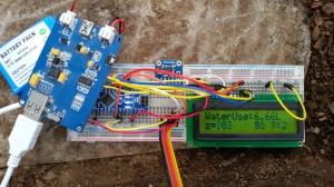
After a few days of running the water meter has worked well. Thoughts have turned to formalizing it with a proper PCB, mounting and how to power it. It currently has a 3000mAh battery and a solar panel for a little help during the day. This ran the Arduino Nano and xbee for 2.5 days before running flat. I found out today when removing the meter (it was flat) the solar panel on an overcast day can run the current setup no problem.  By extending the battery life I can be sure that even if there is extremely bad weather for a few days the meter will not have any outages. So far I have 3 thoughts on reducing power usage:

  • Put the xbee to sleep with a Pin from the nano to save some power in between the minutely broadcast.
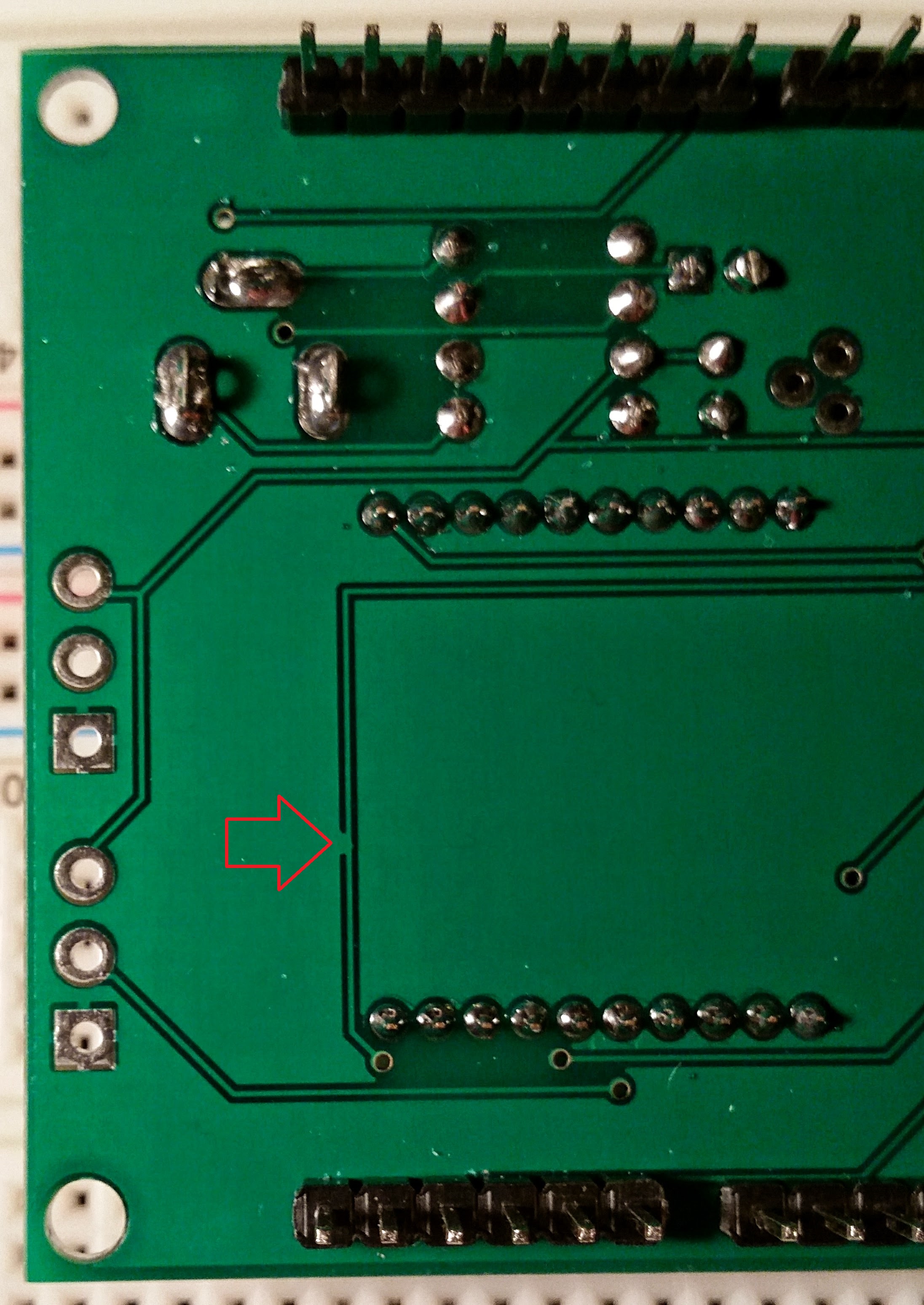
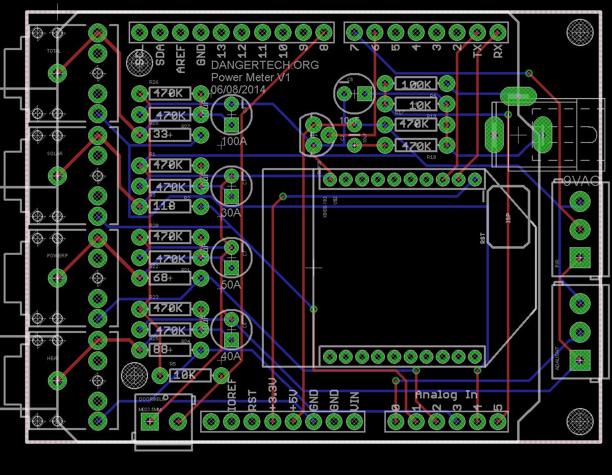
  • Build a custom arduino into the PCB to ditch all the extra component drain that arduinos come with.
  • Put the arduino asleep with the Jeelib library in between sensor reads

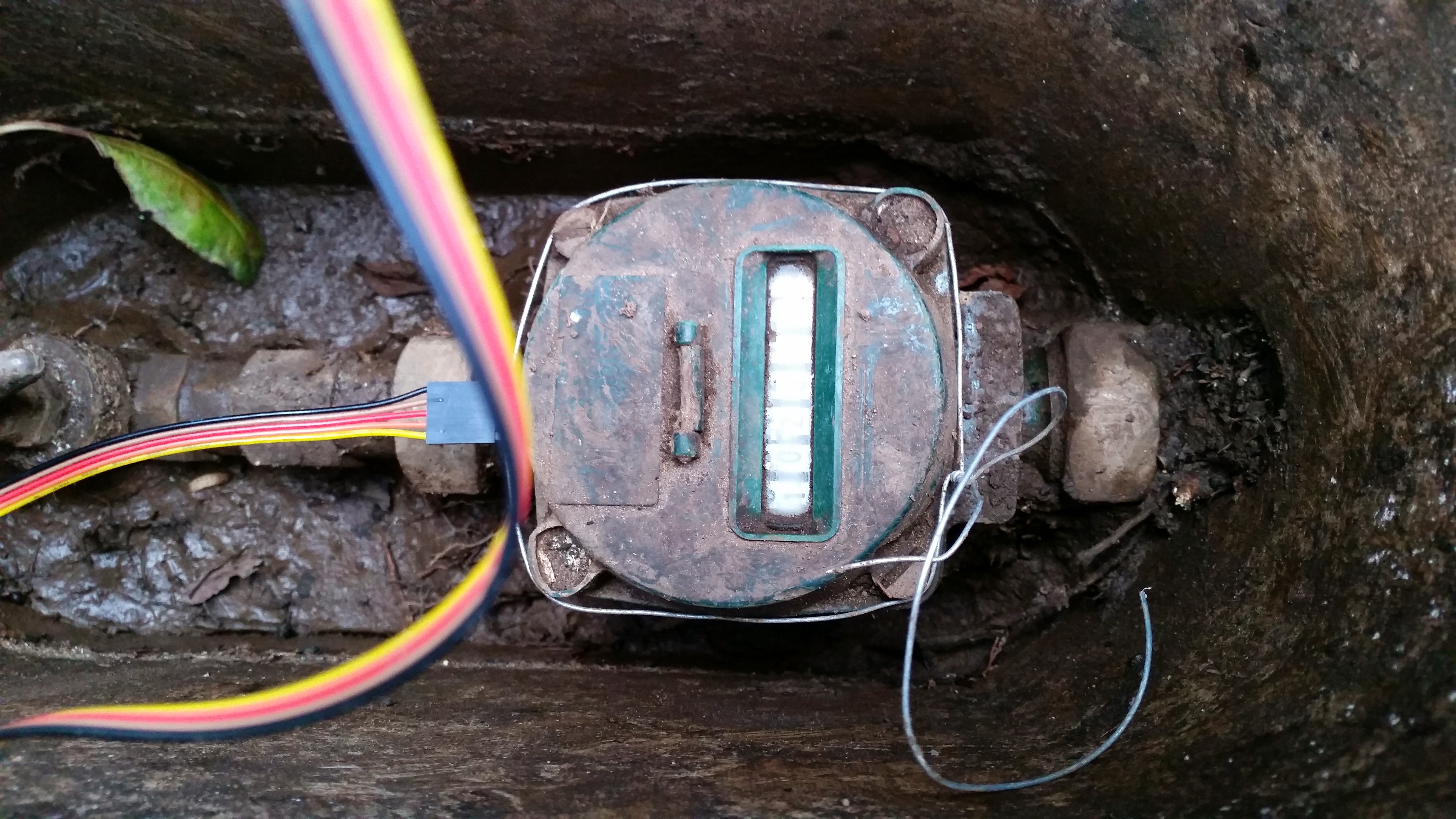
One other problem is the location of the power meter, it is in a very shady spot, more especially when the trees around it get their leaves back from winter. This brings up another option, I could run a wire from the house to power it. What to do? I’m not sure which way I’ll turn yet. In the meantime I will hook up the meter to the multimeter and see how much current it is actually drawing. I’ll be able to actually see how effective the above points will be at reducing power usage.

Posted in Arduino, Electronics, SensorNet | Tagged , , | Leave a comment

Water Metering?

20140913_151630

I’ve had ideas on monitoring the Houses water usage for awhile. The method I was thinking, which was severing the mains and putting a flow meter in between, didn’t sound like the best of ideas. The flow meters I have around don’t really look up to snuff for something as hardcore as monitoring the water mains. Per tap is another thing though. I think they would be great at this. It was then when I was reading through some hackaday.com articles when I came across HackersBench project to monitor is own water usage. He had the fantastic idea of monitoring the magnet that spins around inside the mains water metre with a magnetometer! Surely not I thought, can this really be detected? I wasn’t sure if the magnetometer would be able to get close enough to the magnet to pick up anything. It was damn well worth trying out though. I breadboarded up an Arduino nano, A LCD , a battery pack and a MAX3110 magnetometer.20140913_151630

I banged out some quick code to show the readings on the X,Y and Z axis and went out to test. I ended up having to dig out my meter a bit to get to it better. Amazing how much crud builds up in there. I remembered cleaning it out 3-4 years ago.20140913_151641

I turned a tap on and left it running and ran back to the meter. Holding the sensor in place I fired up the Arduino and…. BINGO! It was easy to see the Sine wave of results appearing on the LCD. Up Down Up Down. This was excellent. I was quite excited. I took the contraption I had built inside and over the next few days have been coding and testing a more permanent solution. I added an XBee to the solutions and updated MotherHubs code to accept the new sensors. The code so far seems robust. Its been running most of  the day with no problems. I made a few changes including calibrating how many of the rotations of the magnet meter it takes for a litre of water to be measured. Hopefully its pretty dead on now. the mains meter is a Davis Shephard type. No model number that I can see and I couldn’t find any Specifications on the net. If anybody else is looking I have it as 57.1428 millilitres per turn of the magnet.

Here are some graphs from Xively.com. Not the best but until I get my own web front end up they tide me over 🙂 These are based over 12 Hours.


Water Usage. Litres per minute
20140913_151641

Water Usage. Litres per Hour
20140913_151641

Water Usage. Litres per Day
20140913_151641

This has completely side tracked me from the PowerArdy project but I have enjoyed it thoroughly. Need to get to work on designing a PCB for it! I have the breadboarded unit inside a lunch box by the meter at the moment. Not sure how long the battery can run it as yet. I’ll have to add battery monitoring next 🙂

Posted in Arduino, Electronics, SensorNet | Tagged , , , , | 3 Comments

PowerArdy Arrives!

2014-09-14 18.59.32


The PCBs arrived from DirtyPCBs.com! They came much faster than the first lot I ordered. I wasn’t expecting them in the 2 weeks they took to come, nevertheless enough of the other parts I needed had come that I could put the main bits together!

20140826_101002


That very night after work I busily got the parts together to solder up…

20140826_205037

Tada! Mostly completed. its still missing the 3 terminals for the doorbell, motion and light detection. They haven’t arrived yet. I made a mistake there and used the wrong spaced terminals. So many parts to choose from in EaglePCB!


2014-09-14 18.59.32

I fitted it into an arduino UNO and quickly got to some testing. Alas, all my results were coming in at zero, something was up! I was out of time and didnt get back to it for another 2 weeks. Seems my code was just a bit off and the library I was using from openenergymonitor.org needed some slight changes. I fixed all that up and I had results! Well 3 results out of the 5. The 9V AC jack was wired wrong but easy to fix with a small piece of wire. The Pink 3.5mm jack above was the other problem. I tested components over and over ruling them out until finally i was following a trace and found this (See red arrow below)

IMG_20140909_231356 (1)


A manufacturing Defect! I could not believe it! I checked the other 9 boards I got from DirtyPCBs and all of them were fine. Just the lucky one I had chosen had the flaw. Ha! This should be easy to fix with some careful scratching of the PCB. I’ve learnt to check over the PCB first before putting the boards together now. Lesson learnt. Not far away now from having very decent power monitoring!

Posted in Arduino, Electronics, SensorNet | Tagged , | Leave a comment

Introducing PowerArdy!

My second PCB Ever has been sent of for fabrication! I’ve been lazy and haven’t posted my first Circuit Board Ever yet. This will replace my Current Cost Envi unit which has been beavering away for a few years now with 2 current Sensors. Since adding Solar to the house 2 isn’t enough. I have one Sensor on the total house power circuit (Mains) and the other around the Heating Circuit which services the Hot water Cylinder and the Heatpump. I pull 3 totals out of this by subtracting the Heat circuit off the total power circuit to give me the leftover which is powerpoints and Lights. There has been some anomalies with this which to be honest I haven’t looked into my code to see if its a bug there or something else. The new PowerArdy has 4 Current sensors on it! They will monitor:

  • Lights and Power
  • Heater Circuit
  • Solar Production
  • Total Power

This will hopefully fix the anomaly with my data. The other problem I have with the old setup is when I have a surplus of power from the solar and it starts exporting to the grid it appears as power consumption on my graphs! No good at all. I’ve also gone pro by adding a 9V AC-AC Powersupply that will monitor the line voltage to calculate power factor. This in turn lets you calculate real power value properly. Also in the mix, as this unit will be by the Front door, I’ve added a PIR sensor for motion detection, a TMP36 temperature sensor, a light sensor and a button. The button is for a coming Doorbell button. Which as it happens is how I started playing with Arduino stuff in the first place! I just wanted a doorbell! I have a lot of trouble hearing anybody at the door which I plan on fixing with a very loud old school Siren I have around here somewhere. Awesome sauce…… once its setup 🙂 Also included is a Xbee to shoot all the data through to motherhub.

Here is the PCB layout of the new board

Capture


I hope its all correct! Will be a 4-8 weeks before I see the boards yet so I have some time to wait. In the meantime I’ve ordered all the other parts I don’t have here. Version 2 of this will probably have a arduino included in the design instead of being an Arduino shield as it is now.

Posted in Arduino, Electronics, SensorNet | Tagged , , , , | 1 Comment

Reading a Serial output from Arduino with Python V1

This is my first try at Python. It reads the Serial Output from Serial 3 on MotherHub. I had some problems with it randomly throwing exceptions, I seemed to have solved that with some If statements that count the amount of variables. The next 24 hours will be the big test as I just set the script up as a service for uninterrupted SQL insertions 🙂 I’m sure this script will expand over the coming months.

import serial
import MySQLdb
import datetime
from time import sleep
 
ser = serial.Serial('/dev/ttyAMA0', 9600, timeout=0) # This is using the serial GPIO pins on the Raspberry Pi, Pins 14 and 15
conn = MySQLdb.connect( host='Your MySQL server IP', db='SensorDB', user='SensorDBUser', passwd='SensorDBPass' ) #Change these to suit
cursor = conn.cursor()
count = 0
 
while True:
 data = ser.read(9999).strip("\r\n")
 parsed = data.split(",")
 sleep(0.5)
 if len(data) >= 54:
 print 'Serial Packet Length:', len(data)
 print 'Got:', data
 print 'parsed:', parsed
 templist = data.split(',')
 print 'Length:', len(templist)
# print templist
 if len(templist) < 12: #If there arent 12 items parsed from the Arduino output string then somethings not right, Go to Jail. Do not pass Go
 print 'ERROR! BZZZZZZZZZ!'
 continue
 else:
 print 'templist[0]:', templist[0]
 print 'templist[1]:', templist[1]
 print 'templist[2]:', templist[2]
 print 'templist[3]:', templist[3]
 print 'templist[4]:', templist[4]
 print 'templist[5]:', templist[5]
 print 'templist[6]:', templist[6]
 print 'templist[7]:', templist[7]
 print 'templist[8]:', templist[8]
 print 'templist[9]:', templist[9]
 print 'templist[10]:', templist[10]
 print 'templist[11]:', templist[11]
 
 # Prepare SQL query to INSERT a record into the database.
 sql = "INSERT INTO tblSensorData(fldCommsMotion, fldCommsTemp, fldCommsBarometer, fldCommsHumidity, fldCommsLux, fldXbee1Temp, fldXbee1Volt, fldXbee1Battery, fldXbee1SolarV, fldTotalPowerUse, fl dHeatuse, fldLightPower) \
 VALUES ('%s', '%s', '%s', '%s', '%s', '%s', '%s', '%s', '%s', '%s', '%s', '%s' )" % \
 (templist[0], templist[1], templist[2], templist[3], templist[4], templist[5], templist[6], templist[7], templist[8], templist[9], templist[10], templist[11])
 print"sql ready for execution"
  # Execute the SQL command
 cursor.execute(sql)
 print"SQL Injected!"
 count = count + 1
 print 'SQL Update Count:', count #This is just so I can easily see how many updates have processed before an exception
# Commit your changes in the database
 conn.commit()
 
#sleep(1)
print 'not blocked'
 
conn.close()
ser.close()

MySQL Data is logging! This is massive motivation to get more sensors online. Even though I don’t have a frontend yet I know the data is there to play with.

SQLData


In my travels with PHPMyAdmin I just noticed it has some basic graphing function! Amazing! When did they add that? Now I’ve noticed a problem with the power records


PHPMyADmin graphI have 2 sensors monitoring Power. One on the mains for the entire house and one on the Heating Circuit which does the hot water cylinder at the Heat pump. To calculate the lights and power circuit I simply minus the Heating circuit off the total power circuit. The graph however is showing that every time the heater comes on the power use for the house drops considerably. This is not correct. The difference between the Heating consumption and the total should always be consistent. I’m tempted to look further into this but at the same time I could put those efforts into completing my new energy monitor. I’ll think on it awhile and see if something comes to me


Posted in Arduino, Computing, Electronics, MySQL, phpMyAdmin, Python, Raspberry Pi, SensorNet | Tagged , , , , , | Leave a comment

Home SensorNet Overview

I have an ongoing project that involves my house and sensors. I’ve been working on and off on this as enthusiasm warrants but failing to actually post anything about it on dangertech. So this is it, I’m going to give a general overview interspersed with pictures as a starting point and see what happens. I plan on sensoring the shit out of my home. Sensors in every room that include at a bare minimum Temperature, motion and light levels. There are many more add-ons I want to achieve including Oven temperatures, Freezer temp, Water flow etc etc etc etc. I love stats and cant get enough.

SensorNet aka. Motherhub is an Arduino Mega2560 that runs the network of Xbees and arduinos around the house which so far consists of:

  • Arduino Mega2560 as MotherHub
  • Arduino UNO as data parser from power meter
  • Xbee Co-Ordinator as base unit for Xbee network
  • Outdoor Xbee Temp Sensor that also reports on battery level and solar Voltage
  • CurrentCost Energy Meter measuirng the mains power and outputting to above UNO

Ha. After listing that it doesn’t look like much for the hours of work I’ve poured in. There are also a few projects not completed enough that they are included in the above list:

Arduino UNO Weather unit

  • Wind Speed
  • Wind Direction
  • Rain Gauge
  • Temperature

This one is a little cheaty as it incorporates some Sparkfun parts. The wind and rain sensor are here and a convenient Ardy shield with some nice code on Github are here. To finish this I need to:

  • Xbee hooked up and coded
  • Power requirements calculated to run from solar and a battery
  • Housing designed and printed/built

Arduino House Foyer Sensor Node 

This is all Bread boarded up and tested. It includes:

  • 2 temperature sensors to monitor the hot water cylinder.
  • Room temp and humidity Sensors
  • Light Sensor
  • Motion Sensor

For completion it needs:

  • PCB to be designed and built
  • An enclosure

Arduino Power Monitor Node
This is to replace my CurrentCost device. It has served really well but since adding Solar to the house I need MOAR(tm) control. I currently monitor total power use and the HydroHeat circuits. The new unit will be capable of monitoring 4 circuits. Solar, power and lights, Hydroheat and Total Power consumption. As this sits by the front door it will also need to act as a doorbell, Light sensor, motion sensor and also temperature while communicating wirelessly to MotherHub through an xbee! A busy unit.

Things left to do:

  • Finish circuit board design
  • Enclosure
  • Arduino Code

Data Logging to MySQL and Web Frontend
Motherhub currently logs to Xively here. I want more control of the data and unlimited logging of that data over time which I haven’t seen offered by anyone else yet(for free). I’m sending data from MotherHub to a Python Script running on a Raspberry Pi at the moment. My NAS has an instance of MYSQL running so I log the data there. I could run python on the NAS or even my linux proxy server so save one device and its power consumption (not that the Pi uses much) but future wise I may move all of the sensor processing to the python script and more powerful Pi. Depends how MotherHub can handle 10-20 Xbees sending in packets and all the sensor processing 🙂 I’ve just made good progress on this by getting data into the database. No doubt I have a lot more time to be spent here.

  • Testing Script robustness when accepting data over serial from MotherHub
  • Running script as daemon on the Pi
  • PHP Front end to display graphs

Learning all this as I go but really starting to have fun with it. PCB design and Python being the latest skills I’ve started learning and have to admit enjoying immensely.

This is a great start to Documenting this whole thing! I have more of a plan after putting this to a post. I will do separate posts dealing individually with the different nodes that will include all the finer details of PCB designs and code. I know I said there would be pictures at the top of this post but i think its long enough already. I will add them in to the detailed posts of each arm of the project.If you have read all this then hopefully future posts can help you achieve your own SensorNet 2000 😛 I want to hear about it!

Posted in Arduino, Electronics, Raspberry Pi, SensorNet | Tagged , , , , , | Leave a comment

Dark Places

IMG_0795

Extending the test code I built-in yesterdays LED post, I’ve  added a PIR motion sensor and a LDR (light detection) What we now have is when motion is detected AND the light level is below a certain level the LED’s will fade on to full brightness, stay on until motion is no longer detected and then fade down until off. A bit sexier than just on and off 🙂 I plan on setting something like this up using LED strips or the 2W LED’s. Living in an older house means that there’s not as many light switches nor sometimes enough lighting in the first place. Some of the hallways and outside entrances could really benefit from some sexy automatic lighting. I will rig something together temporarily soon(tm) to get the light thresholds correct before designing a nice encased unit.

Below is the code as it currently stands. Feel free to recommend improvements!

1
2
3
4
5
6
7
8
9
10
11
12
13
14
15
16
17
18
19
20
21
22
23
24
25
26
27
28
29
30
31
32
33
34
35
36
37
38
39
40
41
42
43
44
45
46
47
48
49
50
51
52
53
54
#define LEDPin 6 //pin feeding TIP120
#define onboardLED 13 //onboard LED for some debugging
#define motionPin 4  //PIR connection
#define fadeSpeed 10 //Adjust how fast slow you want the fade effect to function
#define lightPin 5 //LDR connection
 
int led;
int motion;
int counter = 0;
int light;
 
void setup() {
//set pinmodes
  pinMode(LEDPin, OUTPUT);
  pinMode(onboardLED, OUTPUT);
  pinMode(motionPin, INPUT);
  pinMode(lightPin, INPUT);
  Serial.begin(9600); //start-up serial for outputting debug info
  int motion = LOW;
  led = 0;
 
}
 
void loop() {
 
  light = analogRead(lightPin); //read light levels
  Serial.print("Light Level: "); 
  Serial.println(light);  //send light levels to serial
  motion = digitalRead(motionPin); //read motion from PIR
 
  Serial.print("Motion: "); 
  Serial.println(motion);  //send motion state to serial
  Serial.println(led);
 
  if((light > 500) && (motion == 1)) { //if motion detected and light level below a certain level, do this
    while (led < 255) { //led below full brightness? 
      led++; //increment fade up to full powahs
      analogWrite(LEDPin, led); //write change to LED control Pin into TIP120
      delay(fadeSpeed); 
      break; //need to try this remarked out when arduino is out of testing location
     }
   }   
  else if((motion == 0) && (led > 0)) { //otherwise if motion not detected and led value is on, fade down
    led--; 
    analogWrite(LEDPin, led);
    delay(fadeSpeed);
 
  }
 
  else {
    // delay(250);
    // Serial.println("delay");
  }
}

Links to some Parts:

2W LEDS – DealExtreme
PIR Sensor
 – Deal Extreme
TIP120 Power Darlington Transistors – Adafruit

Posted in Arduino, Electronics | Tagged , , , , , , | Leave a comment

Sidetracked with LED’s

I was playing with some TIP120 Power Darlington transistors trying to bend them to my will, when I got completely sidetracked….. sort of, with Some 2W LED’s I got a while ago.

IMG_0791


These bad boys need to be soldered onto a heat sink as they get pretty hot and die quickly without anyway to dissipate the heat. Luckily i have a billion of them handy. The tricky thing is I need a 1 Ohm resistor….. Lowest I have is a 220 Ohm one (Sad Panda) I remember this huge bad boy resistor from a power supply that was beyond repair (transformer blown) I dug it up and actually found what I needed! There were 3 x 1 Ohm 5W resistors on it! Perfect. Desoldered them and grabbed some thermal compound. Have everything I need now!

IMG_0790

IMG_0792
Once I put them all together I attached them to 12V of Powah to see what we got…

IMG_0795

IMG_0796

The Camera did a great job of turning the Mini Sun into something vaguely view-able in a picture. Every time I glance at it I’m blinded in that part of my eye. Har. Anyway I got sidetracked into this by trying to run a 12V strip of LED’s through the TIP120 so I could fade it in and out. For some reason though whether I pump 12V into it or 15 I am only seeing around 7V entering the LED strip. Whats going on! I needed something else 12V for some testing. 2W LEDs it was! Specs of the 2W LEDs are:

– Power: 2W
– Rated voltage: DC 3.0V~3.2V
– Rated current: 600~650mA
– Brightness: 160~180LM
– Color temperature: 2850~3050K

12V (Supply Voltage)/3V (Rated Voltage) =12V

LEDs always need a resistor in series with them to stop thermal runaway. Other wise I believe, as the LED heats up its resistance lowers allowing more current, which makes it heat up more, which lowers its resistance more, repeat, repeat, supernova. While not necessarily causing a popped LED straight away it will lower the life of the LED considerably. (Disclaimer this info is dredged up from parts of my Brain that are quite old and could be totally wrong! Please correct me if I’m wrong!) The value of the resistor you need to use will change depending on your LED specs and voltage used. Just google for a LED calculator and save yourself some maths.


Anyhoo! Back on track. Using an Arduino Uno and a TIP120 Darlington transistor I setup the same fade I was trying to use on the strip. Low and behold….. Its working fine. I’ll need to grab the data sheet for the TIP120 and see if I can figure out whats going on. I imagine I’m overloading it perhaps.


the Arduino can only supply 5V and around 40mA of current on its Pins so you can’t just run huge Loads of its pins directly. This is where the TIP120 comes in! Using a PWM Pin on the Arduino you can alter the Pins output to vary the voltage output which the TIP120 can use to step your larger voltage by! For example 1V output on the Arduino could be 8V from the Darlington transistor. This can vary on the type of transistor you have of course, check the data sheet.

A video of the pulsing can be seen on YouTube here. I cant figure out how to embed it right now and its getting late!. The humanity! Will come back and fix it later. The fade isn’t quite the whole range of the pulse. I’ve taken the min and max into around 50 –  230

Here is my Arduino code:

#define LEDPin 6
#define onboardLED 13

#define fadeSpeed 10

void setup() {

pinMode(LEDPin, OUTPUT);
pinMode(onboardLED, OUTPUT);
Serial.begin(9600);
}

void loop() {
int led;

// Fade in
for (led = 30; led < 230; led++) {
analogWrite(LEDPin, led);
analogWrite(onboardLED, led);
delay(fadeSpeed);
Serial.println( led );
}

//Fade out
for (led = 230; led > 30; led–) {
analogWrite(LEDPin, led);
analogWrite(onboardLED, led);
delay(fadeSpeed);
Serial.println( led );
}
}

This is all part of a project for some LED lighting around the house hooked up to some motion detectors and LDRs (Light Detecting Resistors?) Instead of just lights on, lights off a nice gentle fade in and out at specified times will look a treat! Moar later!


Posted in Arduino, Electronics | Tagged , , | 1 Comment