By Dan | Published April 28, 2013 | Last Updated April 28, 2013
Further News:
Tried it out again today. Could see it ticking by no probs. Judged the flow meter at its pressure and flow rate to be down by 20%. So every 1 litre pumped into a bucket would only report 0.8 litres on the Arduino This is easily remedied in the Arduino sketch. These flow meters are inaccurate but you can do some controlled tests to improve the accuracy at a certain pressure of water. How much water did I pump you say? Well…… I went a bit low in the tank and sucked up a heap of gunk! The pump loves it but the water flow meter did not. Nothing I did could get it going again. So! Version 3 will require a filter 🙂
By Dan | Published April 27, 2013 | Last Updated April 27, 2013
While I was away it seems I had some rain at home. Septic is half full again! Blast! Missed out on seeing how the water is getting in.
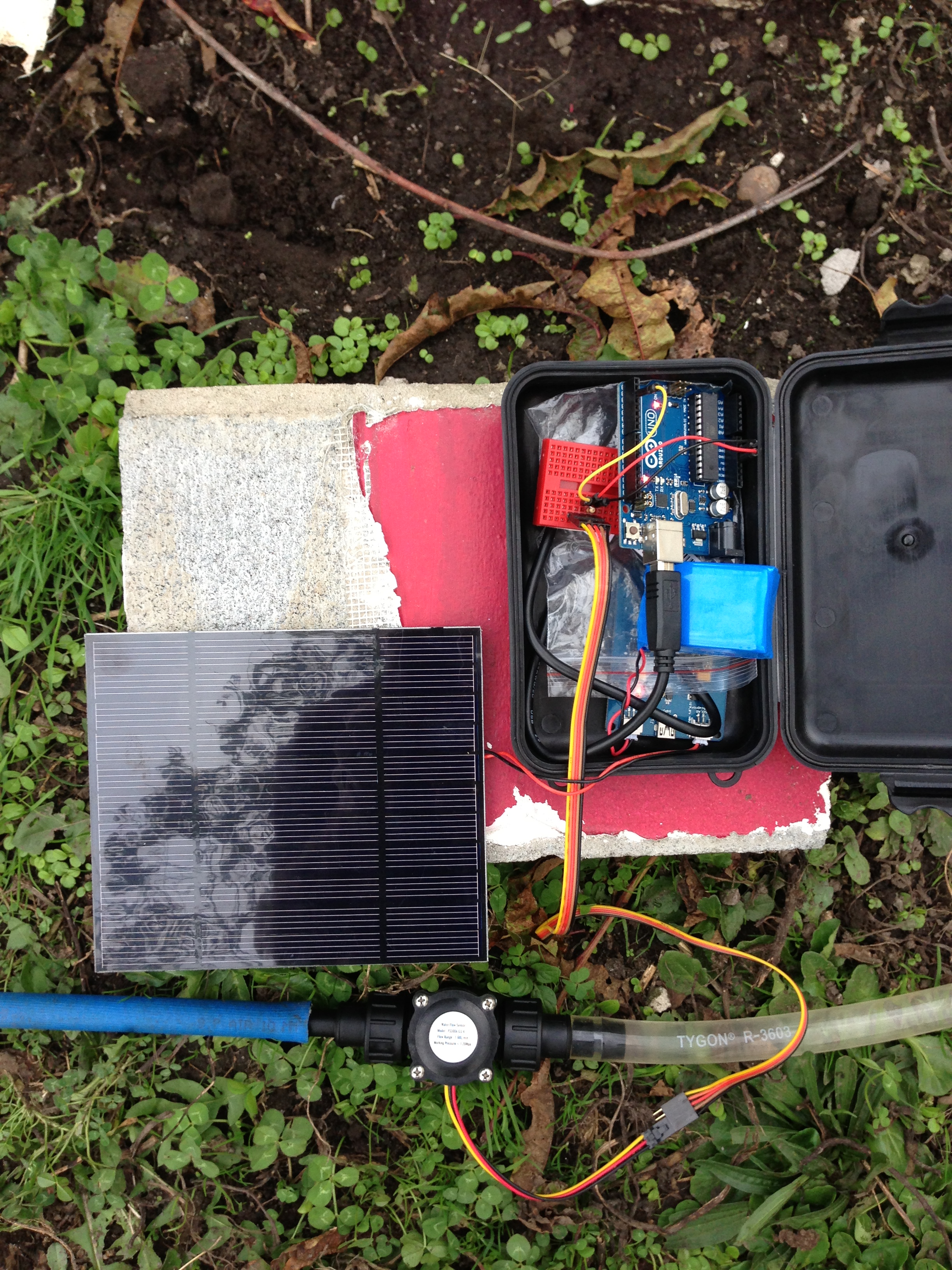
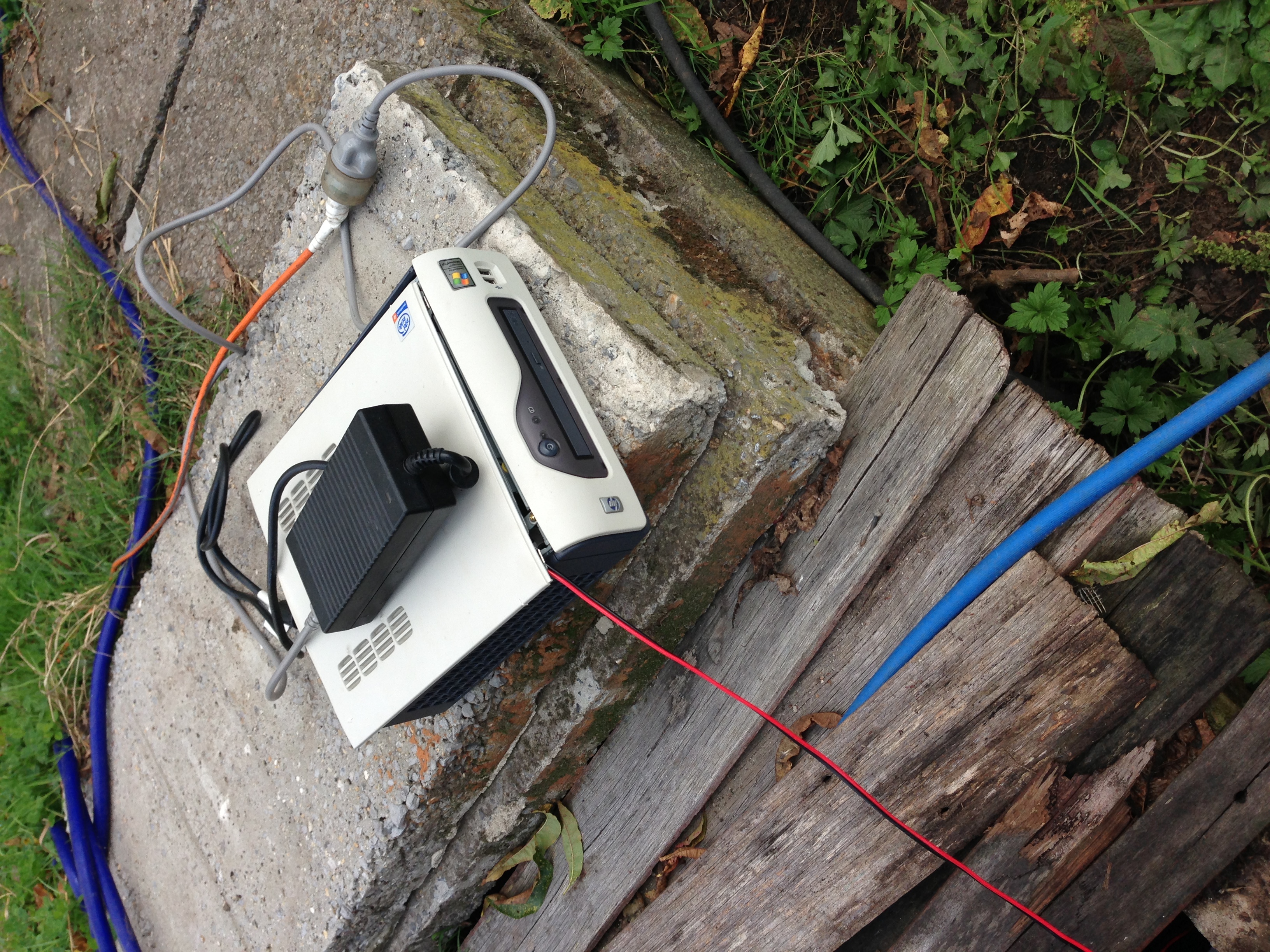
At least I have a good excuse to play with pumps again! This time to spice things up I thought I’d try and monitor how much water gets pumped out! Yeah! You can see in the above shot how small the pump is I’m using…. Does a good job lifting all that water so far. I slapped this beast together:
Crammed in that little box we have a solar lithium battery charger hooked up to a 3.7V 3000mAh Li-ion batter and the biggest solar panel I have laying around….. I forget its watts but know it provides 3.6 on the voltage side of things. This in turn has an Arduino UNO plugged in. Portable powah! Wrangled off that we have a simple cheap water flow meter with a couple of standard poly pipe fittings to attach the hoses to. These can be had from any decent hardware store. It was looking like it may rain thus it all being crammed into the box. The plastic you can see in the box is a precaution to stop any of the circuitry shorting out across the 2 boards.
The pumps in the outlet line and the party is about to start! I had no problem getting the pump primed this time. I dicked around with it a whole lot the last time and got it down pat pretty well. Attach garden hose to output side of hose coming from the pump and push the water flow through backwards until all the air has blown out. Turn pump on and garden hose off and voila! Lots of flow!
That pumped happily for a few hours no problems. Just on dark though it started to really rain so I packed the gear up just short of the tank being empty. No probs! I have stats to check off the Arduino! After unpacking it from the box carefully I realized a flaw in my plan….. How was I do get the data out of it? Ha! Foiled! Rebooting the Arduino would wipe said data. OK that’s great Ill just hook it up to USB and turn the serial port viewer on….NO! That auto causes the Arduino to reboot! Luckily the code I used verbatim from Adafruit had a 2×16 LCD hooked up to it that I decided not to bother with. Cool, cool. A bit more time and we were away…
14.89 Litres?!?!?!?!! What is this black magic! Look at that water flowing in the pic up the page. That’s hundreds of litres over a few hours! Hundreds! I think what happened, and I’m sad to say it but I must of temporarily knocked the power from the little bread board or something. That or there wasn’t enough pressure to spin the water meter. So first attempt = Fail. Second attempt tomorrow shall wield better results. I can monitor it live with the LCD hooked up now.
Here is the code used from Adafruit. You can buy many fantastic things from there so go do it and support a great company /plug over
/**********************************************************
This is example code for using the Adafruit liquid flow meters.
Tested and works great with the Adafruit plastic and brass meters
------> http://www.adafruit.com/products/828
------> http://www.adafruit.com/products/833
Connect the red wire to +5V,
the black wire to common ground
and the yellow sensor wire to pin #2
Adafruit invests time and resources providing this open source code,
please support Adafruit and open-source hardware by purchasing
products from Adafruit!
Written by Limor Fried/Ladyada for Adafruit Industries.
BSD license, check license.txt for more information
All text above must be included in any redistribution
**********************************************************/#include "LiquidCrystal.h"
LiquidCrystal lcd(7,8,9,10,11,12);// which pin to use for reading the sensor? can use any pin!#define FLOWSENSORPIN 2// count how many pulses!volatileuint16_t pulses =0;// track the state of the pulse pinvolatileuint8_t lastflowpinstate;// you can try to keep time of how long it is between pulsesvolatileuint32_t lastflowratetimer =0;// and use that to calculate a flow ratevolatilefloat flowrate;// Interrupt is called once a millisecond, looks for any pulses from the sensor!
SIGNAL(TIMER0_COMPA_vect){uint8_t x = digitalRead(FLOWSENSORPIN);if(x == lastflowpinstate){
lastflowratetimer++;return;// nothing changed!}if(x == HIGH){//low to high transition!
pulses++;}
lastflowpinstate = x;
flowrate =1000.0;
flowrate /= lastflowratetimer;// in hertz
lastflowratetimer =0;}void useInterrupt(boolean v){if(v){// Timer0 is already used for millis() - we'll just interrupt somewhere// in the middle and call the "Compare A" function above
OCR0A =0xAF;
TIMSK0 |= _BV(OCIE0A);}else{// do not call the interrupt function COMPA anymore
TIMSK0 &= ~_BV(OCIE0A);}}void setup(){
Serial.begin(9600);
Serial.print("Flow sensor test!");
lcd.begin(16,2);
pinMode(FLOWSENSORPIN, INPUT);
digitalWrite(FLOWSENSORPIN, HIGH);
lastflowpinstate = digitalRead(FLOWSENSORPIN);
useInterrupt(true);}void loop()// run over and over again{
lcd.setCursor(0,0);
lcd.print("Pulses:"); lcd.print(pulses, DEC);
lcd.print(" Hz:");
lcd.print(flowrate);//lcd.print(flowrate);
Serial.print("Freq: "); Serial.println(flowrate);
Serial.print("Pulses: "); Serial.println(pulses, DEC);// if a plastic sensor use the following calculation// Sensor Frequency (Hz) = 7.5 * Q (Liters/min)// Liters = Q * time elapsed (seconds) / 60 (seconds/minute)// Liters = (Frequency (Pulses/second) / 7.5) * time elapsed (seconds) / 60// Liters = Pulses / (7.5 * 60)float liters = pulses;
liters /=7.5;
liters /=60.0;/*
// if a brass sensor use the following calculation
float liters = pulses;
liters /= 8.1;
liters -= 6;
liters /= 60.0;
*/
Serial.print(liters); Serial.println(" Liters");
lcd.setCursor(0,1);
lcd.print(liters); lcd.print(" Litres ");
delay(100);}
/**********************************************************
This is example code for using the Adafruit liquid flow meters.

Tested and works great with the Adafruit plastic and brass meters
    ------> http://www.adafruit.com/products/828
    ------> http://www.adafruit.com/products/833

Connect the red wire to +5V,
the black wire to common ground
and the yellow sensor wire to pin #2

Adafruit invests time and resources providing this open source code,
please support Adafruit and open-source hardware by purchasing
products from Adafruit!

Written by Limor Fried/Ladyada  for Adafruit Industries.
BSD license, check license.txt for more information
All text above must be included in any redistribution
**********************************************************/
#include "LiquidCrystal.h"
LiquidCrystal lcd(7, 8, 9, 10, 11, 12);

// which pin to use for reading the sensor? can use any pin!
#define FLOWSENSORPIN 2

// count how many pulses!
volatile uint16_t pulses = 0;
// track the state of the pulse pin
volatile uint8_t lastflowpinstate;
// you can try to keep time of how long it is between pulses
volatile uint32_t lastflowratetimer = 0;
// and use that to calculate a flow rate
volatile float flowrate;
// Interrupt is called once a millisecond, looks for any pulses from the sensor!
SIGNAL(TIMER0_COMPA_vect) {
  uint8_t x = digitalRead(FLOWSENSORPIN);

  if (x == lastflowpinstate) {
    lastflowratetimer++;
    return; // nothing changed!
  }

  if (x == HIGH) {
    //low to high transition!
    pulses++;
  }
  lastflowpinstate = x;
  flowrate = 1000.0;
  flowrate /= lastflowratetimer;  // in hertz
  lastflowratetimer = 0;
}

void useInterrupt(boolean v) {
  if (v) {
    // Timer0 is already used for millis() - we'll just interrupt somewhere
    // in the middle and call the "Compare A" function above
    OCR0A = 0xAF;
    TIMSK0 |= _BV(OCIE0A);
  } else {
    // do not call the interrupt function COMPA anymore
    TIMSK0 &= ~_BV(OCIE0A);
  }
}

void setup() {
   Serial.begin(9600);
   Serial.print("Flow sensor test!");
   lcd.begin(16, 2);

   pinMode(FLOWSENSORPIN, INPUT);
   digitalWrite(FLOWSENSORPIN, HIGH);
   lastflowpinstate = digitalRead(FLOWSENSORPIN);
   useInterrupt(true);
}

void loop()                     // run over and over again
{
  lcd.setCursor(0, 0);
  lcd.print("Pulses:"); lcd.print(pulses, DEC);
  lcd.print(" Hz:");
  lcd.print(flowrate);
  //lcd.print(flowrate);
  Serial.print("Freq: "); Serial.println(flowrate);
  Serial.print("Pulses: "); Serial.println(pulses, DEC);

  // if a plastic sensor use the following calculation
  // Sensor Frequency (Hz) = 7.5 * Q (Liters/min)
  // Liters = Q * time elapsed (seconds) / 60 (seconds/minute)
  // Liters = (Frequency (Pulses/second) / 7.5) * time elapsed (seconds) / 60
  // Liters = Pulses / (7.5 * 60)
  float liters = pulses;
  liters /= 7.5;
  liters /= 60.0;

/*
  // if a brass sensor use the following calculation
  float liters = pulses;
  liters /= 8.1;
  liters -= 6;
  liters /= 60.0;
*/
  Serial.print(liters); Serial.println(" Liters");
  lcd.setCursor(0, 1);
  lcd.print(liters); lcd.print(" Litres        ");

  delay(100);
}
By Dan | Published April 26, 2013 | Last Updated April 26, 2013
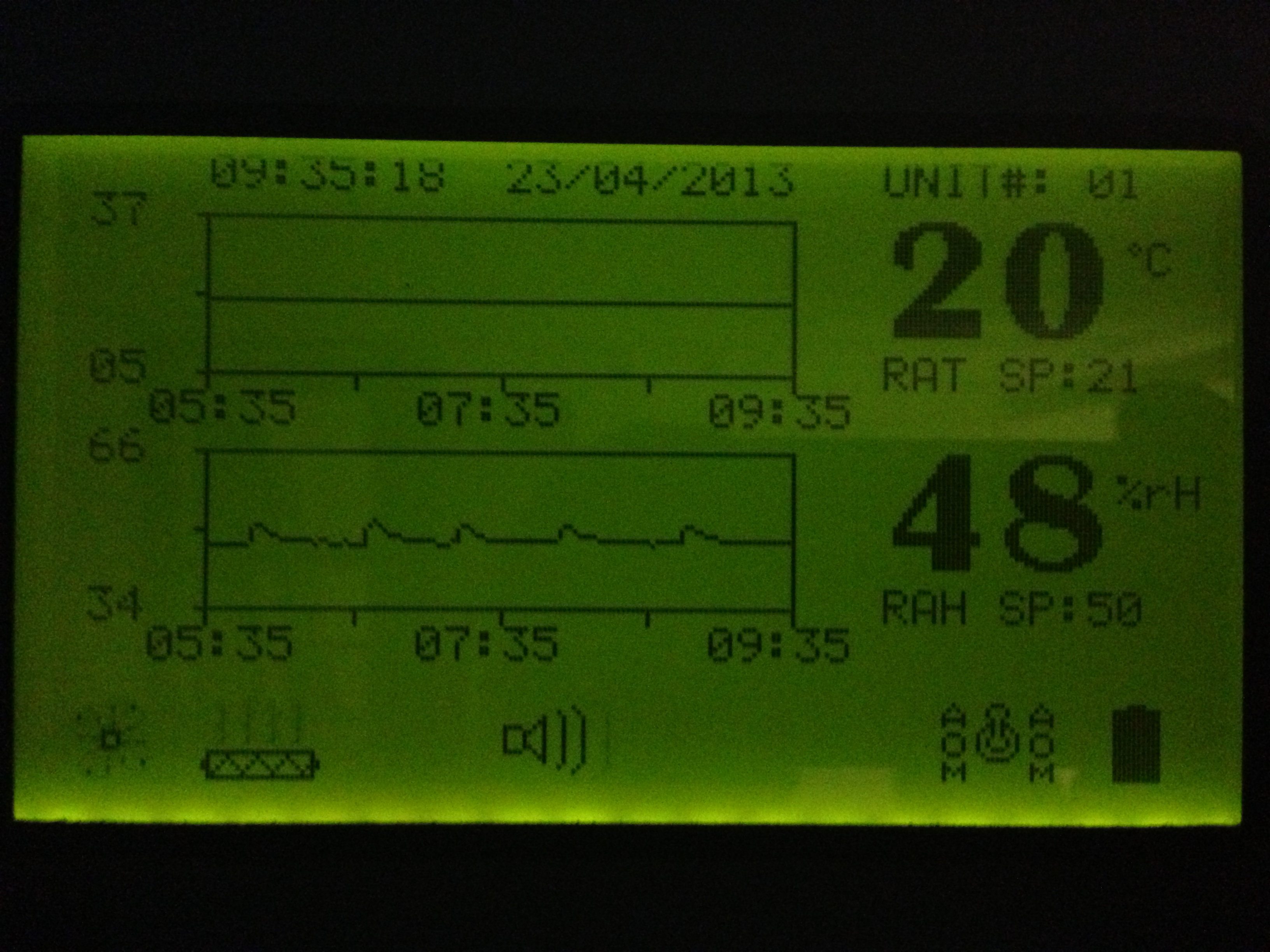
While I was off Parading around in New Zealand (15/04 – 26/04/2013) I came across this bad boy:
Not only is it the biggest resolution(?x?) Graphic LCD I’ve seen but also made use of, in a most awesome way. Information is displayed in an easy to read way and look! Graphs! I had actually been thinking of the same type of graphs for another project I have been working on. I figured out how to do the code side but needed a Real Time Clock (RTC) for the Arduino and a SD Card reader/writer so couldn’t bring to fruition. Fear not however! These items have since arrived at my door so I can try and bring it to life! More on that project later……
By the way, this display was utilized on an industrial sized Air Conditioner unit. Probably around 10 years old.
By Dan | Published April 11, 2013 | Last Updated April 11, 2013
IMG_0795
Extending the test code I built-in yesterdays LED post, I’ve added a PIR motion sensor and a LDR (light detection) What we now have is when motion is detected AND the light level is below a certain level the LED’s will fade on to full brightness, stay on until motion is no longer detected and then fade down until off. A bit sexier than just on and off 🙂 I plan on setting something like this up using LED strips or the 2W LED’s. Living in an older house means that there’s not as many light switches nor sometimes enough lighting in the first place. Some of the hallways and outside entrances could really benefit from some sexy automatic lighting. I will rig something together temporarily soon(tm) to get the light thresholds correct before designing a nice encased unit.
Below is the code as it currently stands. Feel free to recommend improvements!
#define LEDPin 6 //pin feeding TIP120#define onboardLED 13 //onboard LED for some debugging#define motionPin 4 //PIR connection#define fadeSpeed 10 //Adjust how fast slow you want the fade effect to function#define lightPin 5 //LDR connectionint led;int motion;int counter =0;int light;void setup(){//set pinmodes
pinMode(LEDPin, OUTPUT);
pinMode(onboardLED, OUTPUT);
pinMode(motionPin, INPUT);
pinMode(lightPin, INPUT);
Serial.begin(9600);//start-up serial for outputting debug infoint motion = LOW;
led =0;}void loop(){
light = analogRead(lightPin);//read light levels
Serial.print("Light Level: ");
Serial.println(light);//send light levels to serial
motion = digitalRead(motionPin);//read motion from PIR
Serial.print("Motion: ");
Serial.println(motion);//send motion state to serial
Serial.println(led);if((light >500)&&(motion ==1)){//if motion detected and light level below a certain level, do thiswhile(led <255){//led below full brightness?
led++;//increment fade up to full powahs
analogWrite(LEDPin, led);//write change to LED control Pin into TIP120
delay(fadeSpeed);break;//need to try this remarked out when arduino is out of testing location}}elseif((motion ==0)&&(led >0)){//otherwise if motion not detected and led value is on, fade down
led--;
analogWrite(LEDPin, led);
delay(fadeSpeed);}else{// delay(250);// Serial.println("delay");}}
#define LEDPin 6 //pin feeding TIP120
#define onboardLED 13 //onboard LED for some debugging
#define motionPin 4  //PIR connection
#define fadeSpeed 10 //Adjust how fast slow you want the fade effect to function
#define lightPin 5 //LDR connection

int led;
int motion;
int counter = 0;
int light;

void setup() {
//set pinmodes
  pinMode(LEDPin, OUTPUT);
  pinMode(onboardLED, OUTPUT);
  pinMode(motionPin, INPUT);
  pinMode(lightPin, INPUT);
  Serial.begin(9600); //start-up serial for outputting debug info
  int motion = LOW;
  led = 0;

}

void loop() {

  light = analogRead(lightPin); //read light levels
  Serial.print("Light Level: ");
  Serial.println(light);  //send light levels to serial
  motion = digitalRead(motionPin); //read motion from PIR

  Serial.print("Motion: ");
  Serial.println(motion);  //send motion state to serial
  Serial.println(led);

  if((light > 500) && (motion == 1)) { //if motion detected and light level below a certain level, do this
    while (led < 255) { //led below full brightness?
      led++; //increment fade up to full powahs
      analogWrite(LEDPin, led); //write change to LED control Pin into TIP120
      delay(fadeSpeed);
      break; //need to try this remarked out when arduino is out of testing location
     }
   }
  else if((motion == 0) && (led > 0)) { //otherwise if motion not detected and led value is on, fade down
    led--;
    analogWrite(LEDPin, led);
    delay(fadeSpeed);

  }

  else {
    // delay(250);
    // Serial.println("delay");
  }
}
By Dan | Published April 9, 2013 | Last Updated April 10, 2013
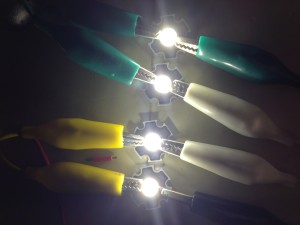
I was playing with some TIP120 Power Darlington transistors trying to bend them to my will, when I got completely sidetracked….. sort of, with Some 2W LED’s I got a while ago.
These bad boys need to be soldered onto a heat sink as they get pretty hot and die quickly without anyway to dissipate the heat. Luckily i have a billion of them handy. The tricky thing is I need a 1 Ohm resistor….. Lowest I have is a 220 Ohm one (Sad Panda) I remember this huge bad boy resistor from a power supply that was beyond repair (transformer blown) I dug it up and actually found what I needed! There were 3 x 1 Ohm 5W resistors on it! Perfect. Desoldered them and grabbed some thermal compound. Have everything I need now!
Once I put them all together I attached them to 12V of Powah to see what we got…
The Camera did a great job of turning the Mini Sun into something vaguely view-able in a picture. Every time I glance at it I’m blinded in that part of my eye. Har. Anyway I got sidetracked into this by trying to run a 12V strip of LED’s through the TIP120 so I could fade it in and out. For some reason though whether I pump 12V into it or 15 I am only seeing around 7V entering the LED strip. Whats going on! I needed something else 12V for some testing. 2W LEDs it was! Specs of the 2W LEDs are:
– Power: 2W
– Rated voltage: DC 3.0V~3.2V
– Rated current: 600~650mA
– Brightness: 160~180LM
– Color temperature: 2850~3050K
12V (Supply Voltage)/3V (Rated Voltage) =12V
LEDs always need a resistor in series with them to stop thermal runaway. Other wise I believe, as the LED heats up its resistance lowers allowing more current, which makes it heat up more, which lowers its resistance more, repeat, repeat, supernova. While not necessarily causing a popped LED straight away it will lower the life of the LED considerably. (Disclaimer this info is dredged up from parts of my Brain that are quite old and could be totally wrong! Please correct me if I’m wrong!) The value of the resistor you need to use will change depending on your LED specs and voltage used. Just google for a LED calculator and save yourself some maths.
Anyhoo! Back on track. Using an Arduino Uno and a TIP120 Darlington transistor I setup the same fade I was trying to use on the strip. Low and behold….. Its working fine. I’ll need to grab the data sheet for the TIP120 and see if I can figure out whats going on. I imagine I’m overloading it perhaps.
the Arduino can only supply 5V and around 40mA of current on its Pins so you can’t just run huge Loads of its pins directly. This is where the TIP120 comes in! Using a PWM Pin on the Arduino you can alter the Pins output to vary the voltage output which the TIP120 can use to step your larger voltage by! For example 1V output on the Arduino could be 8V from the Darlington transistor. This can vary on the type of transistor you have of course, check the data sheet.
A video of the pulsing can be seen on YouTube here. I cant figure out how to embed it right now and its getting late!. The humanity! Will come back and fix it later. The fade isn’t quite the whole range of the pulse. I’ve taken the min and max into around 50 – 230
// Fade in
for (led = 30; led < 230; led++) {
analogWrite(LEDPin, led);
analogWrite(onboardLED, led);
delay(fadeSpeed);
Serial.println( led );
}
//Fade out
for (led = 230; led > 30; led–) {
analogWrite(LEDPin, led); analogWrite(onboardLED, led); delay(fadeSpeed); Serial.println( led );
}
}
This is all part of a project for some LED lighting around the house hooked up to some motion detectors and LDRs (Light Detecting Resistors?) Instead of just lights on, lights off a nice gentle fade in and out at specified times will look a treat! Moar later!
By Dan | Published April 8, 2013 | Last Updated April 8, 2013
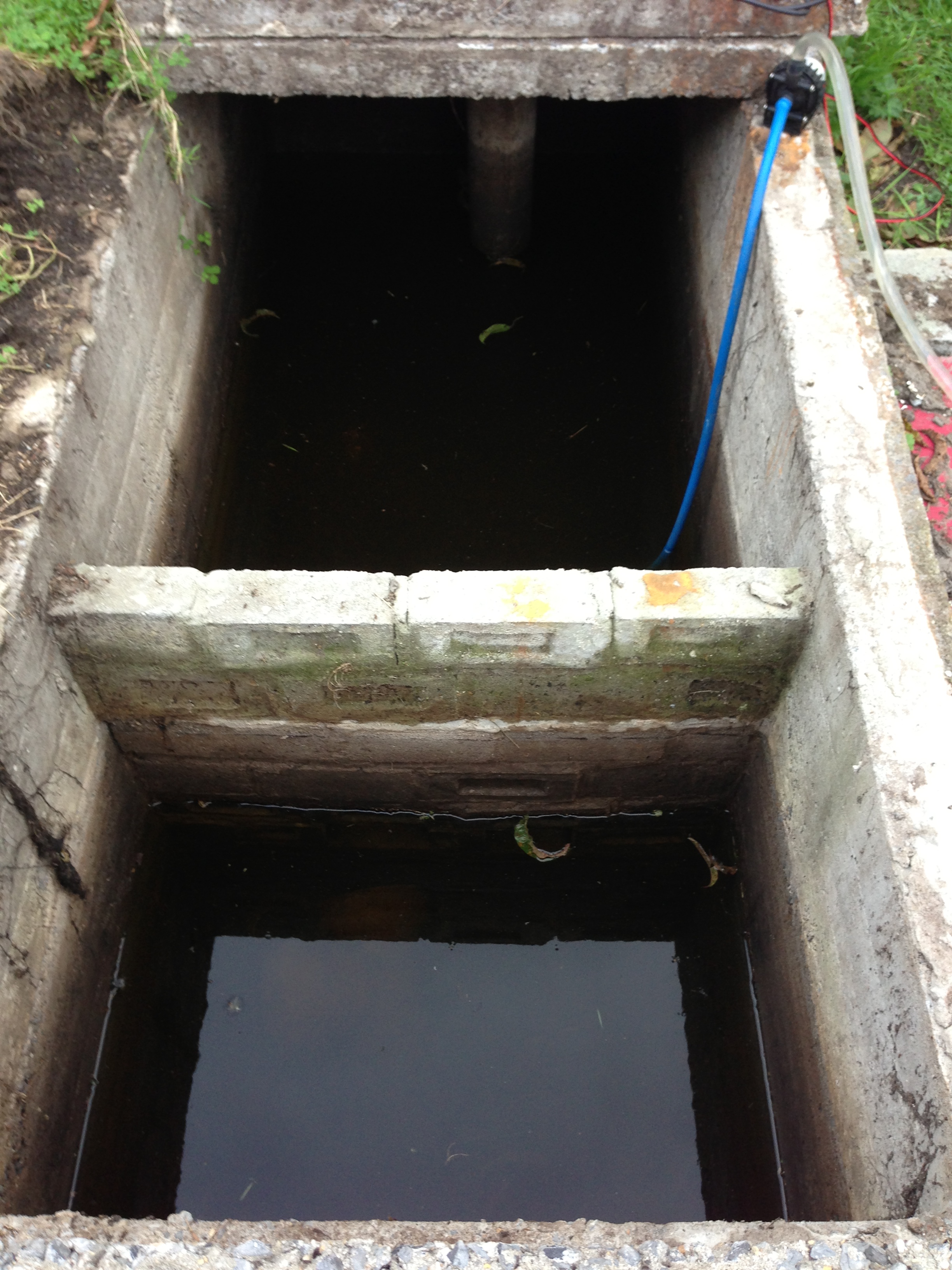
There is an old concrete Septic tank rearing its head out of the ground in the backyard. The only constructive thing I could think of to utilize it better is make a pond. Other than hiding bodies that is. I popped one of the concrete slabs off the top some time ago to see what could be seen. Lots of mosquito lavae and a roughly 2 metre deep concrete box! Short term I purchased 6 goldfish to put in there to wage war against the mosquito horde that was breeding in there. They did a terribly efficient job of that. and am happy to say about a year later 4 very fat healthy goldfish were removed from the tank! I imagine given some time the gold fish will grow quite large given the huge tank they have.
The water and bottom of the tank were quite clean as the tank has not been used for quite sometime in an effluent nature. Scraping around in the bottom of the tank didn’t stir up anything initially. I’ve been giving the backyard a bit of an overhaul lately and decided that while I was working on some other things out there I may as well be draining the tank. I had previously swapped an old computer motherboard I wasn’t using for a water pump that was also being used in a water cooling setup for a computer. The plan being to use it to pump out the water in the septic one day. The little blighter did a bloody good job considering the amount of lift it had to pump up. It took a bit of fiddling to get all the air out but a bit of Macgyver action involving some poly pipe fittings and garden hoses soon had a reliable way of priming the pump. It basically involved hooking the mains water up to the pump outlet pipe and forcing through a heap of water to clear the air locks then disconnecting the outlet pipe to let the water flow in the right direction.
Being used in a PC meant the pump was 12 volts. I know I have some old ATX power supplies around somewhere but a quick look revealed I had no idea which tub they were stored in. So I just grabbed an old PC I had handy and popped the side off to connect the pump to one of the convenient molex connectors within. Nice small form factor made it a breeze to carry in and out of the shed a couple of time.
You can see it had quite an output at first when the water was closer to the top. This steadily declined as the water level in the tank dropped. It had the tank pumped out with only a few centremetres of water left above the mud that had accumulated in the year or so since I first popped open the tank. You can see below also Kaiser Helping excavate a drainage ditch to stop the water accumulating.
While it was busy being emptied I swondered how the hell I was going to get the fish out with not even a small net handy. Kitchen sieve macgyvered onto an old paint roller handle to the rescue! (Note to self: Buy new Kitchen Sieve before anyone notices it missing) This worked well! Also managed to scoop out some of the mud at the bottom. Mainly old leaves and nectarines that had fallen in from the overhanging nectarine tree.
The tank is all empty now the next steps are to block off the inlet and outlet pipes inside so the tank can fill right up to the brim. It currently fills up from ground water seeping in to about 20cm from the top, it will then slowly seep out to about 40-50cm below the top line after some time with no rain. Hopefully it will rain soon too so I can monitor where the water gets into the tank. I imagine it simply soaks through the cement. It’s possible its coming in through the inlet or something weird though. The house was built in the 1940’s so who knows? I do know the tank remains consistently full all year so there doesn’t seem to be much of a problem with water draining out of it. Once i know it can retain water to the brim I have my eye on some sheets of 100 x 100mm square high tensile mesh. I’ll cut this to size and dynabolt it into the tank about a foot down from the top of the tank. This is for safety reasons. There’s nothing like a 2 metre pit of doom to keep you on your toes. I could also never let any kids near the back yard unsupervised with a clear conscious. It will however give somewhere to put some water plant pots and still allow the fish to swim through when they turn into giant mutant sized terrors of the deep.
By Dan | Published April 7, 2013 | Last Updated April 7, 2013
I was happily digging away at some bulbs I need to relocate/give away when BAM! I came across some MONSTER bulbs! I’m not sure what they are but have a feeling they are Agapantha bulbs. This is strange however as they dont quite look the same as the bottoms of the Agapanthas I have growing elsewhere. Also they appear to have been dormant for some time. Maybe because they were wedged in a pack of the other bulbs I was clearing.
Here is what I’m talking about:
It’s a Behemoth! I’ll chuck it in a pot soon and see what we get. In the meantime, does anyone know what it is?