I was playing with some TIP120 Power Darlington transistors trying to bend them to my will, when I got completely sidetracked….. sort of, with Some 2W LED’s I got a while ago.
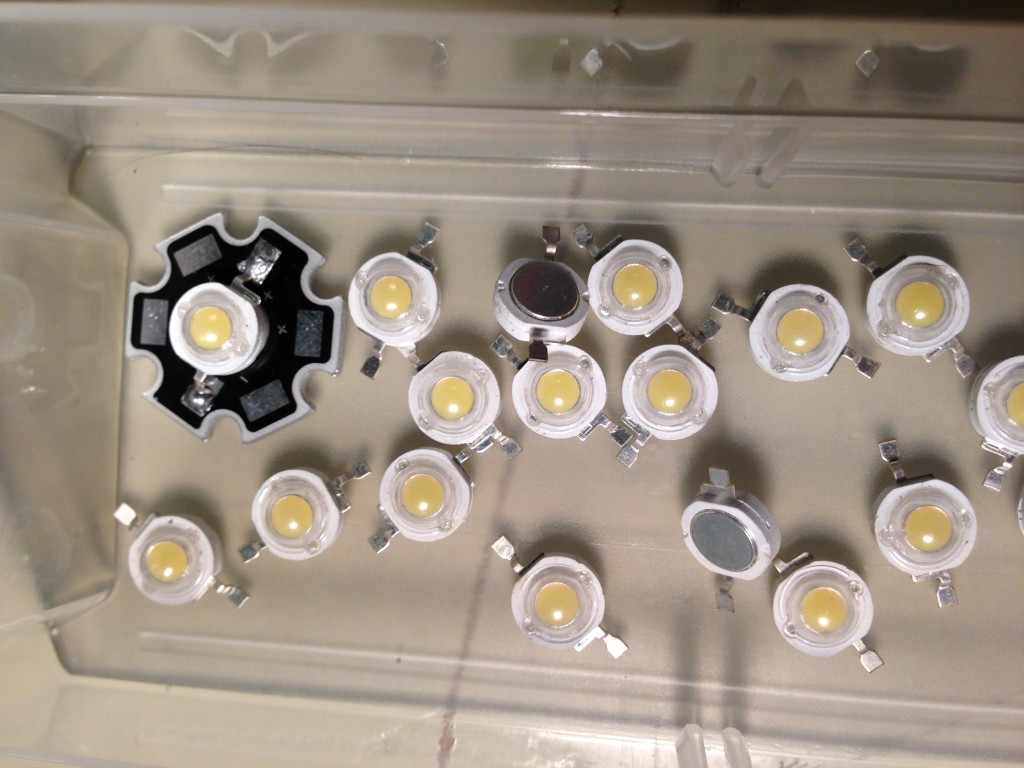
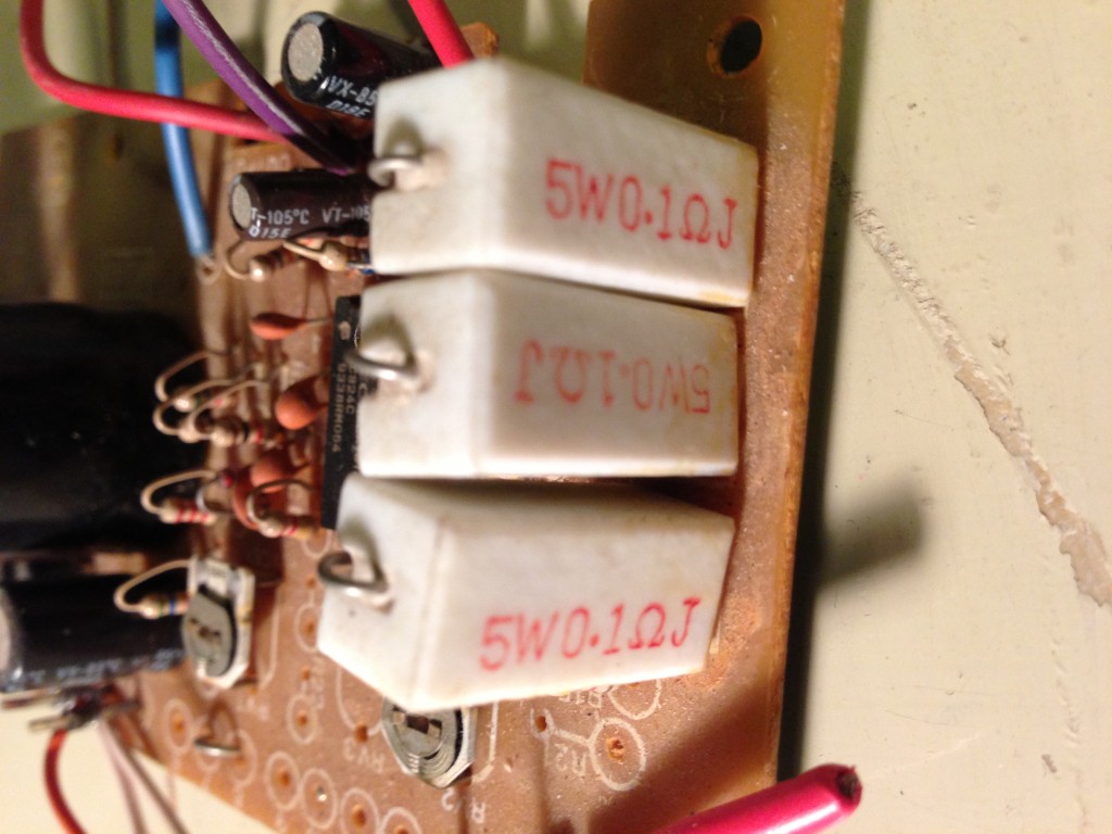
These bad boys need to be soldered onto a heat sink as they get pretty hot and die quickly without anyway to dissipate the heat. Luckily i have a billion of them handy. The tricky thing is I need a 1 Ohm resistor….. Lowest I have is a 220 Ohm one (Sad Panda) I remember this huge bad boy resistor from a power supply that was beyond repair (transformer blown) I dug it up and actually found what I needed! There were 3 x 1 Ohm 5W resistors on it! Perfect. Desoldered them and grabbed some thermal compound. Have everything I need now!
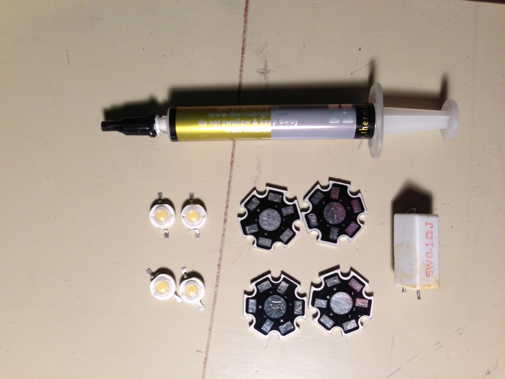
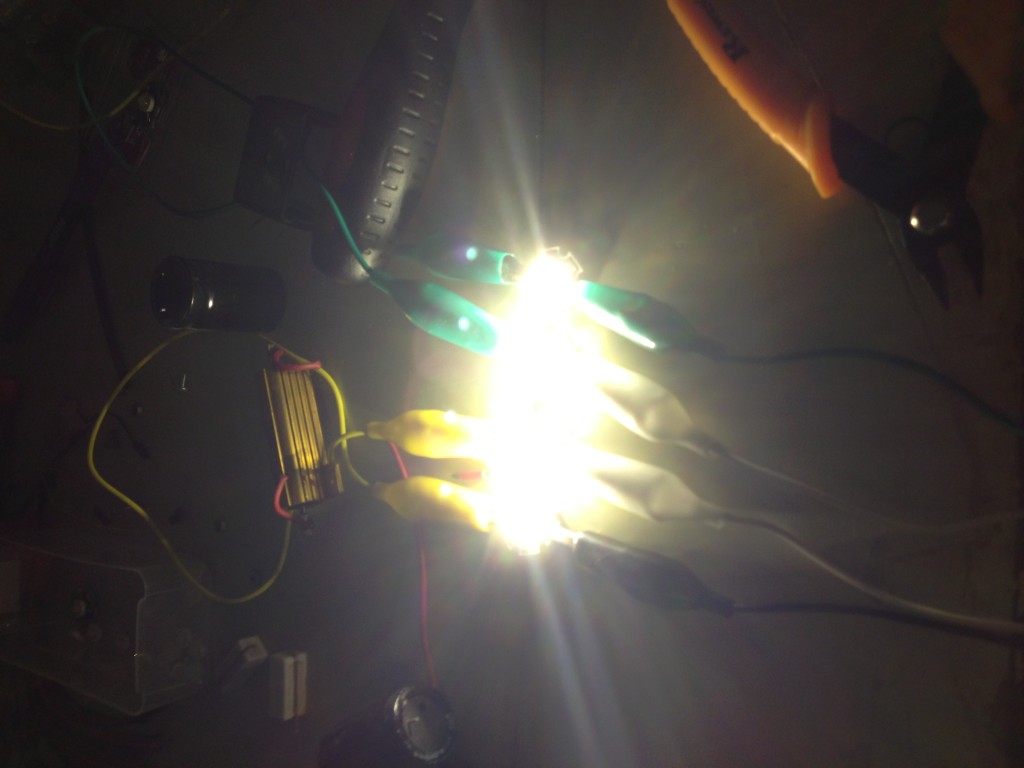
Once I put them all together I attached them to 12V of Powah to see what we got…
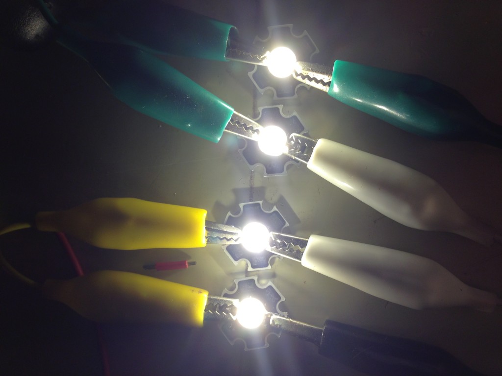
The Camera did a great job of turning the Mini Sun into something vaguely view-able in a picture. Every time I glance at it I’m blinded in that part of my eye. Har. Anyway I got sidetracked into this by trying to run a 12V strip of LED’s through the TIP120 so I could fade it in and out. For some reason though whether I pump 12V into it or 15 I am only seeing around 7V entering the LED strip. Whats going on! I needed something else 12V for some testing. 2W LEDs it was! Specs of the 2W LEDs are:
– Power: 2W
– Rated voltage: DC 3.0V~3.2V
– Rated current: 600~650mA
– Brightness: 160~180LM
– Color temperature: 2850~3050K
12V (Supply Voltage)/3V (Rated Voltage) =12V
LEDs always need a resistor in series with them to stop thermal runaway. Other wise I believe, as the LED heats up its resistance lowers allowing more current, which makes it heat up more, which lowers its resistance more, repeat, repeat, supernova. While not necessarily causing a popped LED straight away it will lower the life of the LED considerably. (Disclaimer this info is dredged up from parts of my Brain that are quite old and could be totally wrong! Please correct me if I’m wrong!) The value of the resistor you need to use will change depending on your LED specs and voltage used. Just google for a LED calculator and save yourself some maths.
Anyhoo! Back on track. Using an Arduino Uno and a TIP120 Darlington transistor I setup the same fade I was trying to use on the strip. Low and behold….. Its working fine. I’ll need to grab the data sheet for the TIP120 and see if I can figure out whats going on. I imagine I’m overloading it perhaps.
the Arduino can only supply 5V and around 40mA of current on its Pins so you can’t just run huge Loads of its pins directly. This is where the TIP120 comes in! Using a PWM Pin on the Arduino you can alter the Pins output to vary the voltage output which the TIP120 can use to step your larger voltage by! For example 1V output on the Arduino could be 8V from the Darlington transistor. This can vary on the type of transistor you have of course, check the data sheet.
A video of the pulsing can be seen on YouTube here. I cant figure out how to embed it right now and its getting late!. The humanity! Will come back and fix it later. The fade isn’t quite the whole range of the pulse. I’ve taken the min and max into around 50 – 230
Here is my Arduino code:
#define LEDPin 6
#define onboardLED 13#define fadeSpeed 10
void setup() {
pinMode(LEDPin, OUTPUT);
pinMode(onboardLED, OUTPUT);
Serial.begin(9600);
}void loop() {
int led;// Fade in
for (led = 30; led < 230; led++) {
analogWrite(LEDPin, led);
analogWrite(onboardLED, led);
delay(fadeSpeed);
Serial.println( led );
}//Fade out
for (led = 230; led > 30; led–) {
analogWrite(LEDPin, led);
analogWrite(onboardLED, led);
delay(fadeSpeed);
Serial.println( led );
}
}
This is all part of a project for some LED lighting around the house hooked up to some motion detectors and LDRs (Light Detecting Resistors?) Instead of just lights on, lights off a nice gentle fade in and out at specified times will look a treat! Moar later!
1 Trackback
[…] the test code I built-in yesterdays LED post, I’ve added a PIR motion sensor and a LDR (light detection) What we now have is when motion […]